At Jingxin 15+ years experience in Plastic injection molding and custom mold & parts in China, Fast lead time and on time delivery from start to finishes
Maybe you got the comments from plastic injection molding factory to say the parts should be modified somewhere. Why? The suggestion from factory engineer is basing on thermoplastic injection molding to meet the injection mold production and part function requirement. So you will know why it is after you read the following tips for plastic parts for injection molding.This is a clear Design guidelines for plastic Injection molded parts.
While designing plastic part, in achieving quality, consistency and productivity must be considered. It is wrong to assume that shapes can be molded successfully without any defects. All shapes may not be 100% molded. To improve the injection molding process has to be understood in depth. We JINGXIN precision machinery limited share some tips here basing on our 10 years experience of injection mold manufacturing. We do hope it can help you on injection molded parts design if you have a new project that needs a plastic parts. Please click here to Learn more about what is plastic injection molding and China plastic injection molding case study. Hereby There a design guidelines for plastic injection molded parts, contains 14 key factors as the below.
1.Wall Thickness:
Plastic parts wall thickness (the overall shell) is usually around 0.80-3.00mm. If too thick then easy to shrink and produce bubbles, too thin difficult to go full of plastic. Large product thickness is thicker, small Product is thinner, the general product to take 1.0-2.0mm thickness for more. And the thickness of products to be as uniform as possible, in the case of special construction design, Some place may be appropriate thick or thinner. But the need to change cannot be mutated, to not shrink and can go full of the cavity in the mold for the principle of general injection process required. If the thickness of less than 0.3mm, it is difficult to full fill injection, but the soft rubber and rubber in the 0.2-0.3mm can do in some case.
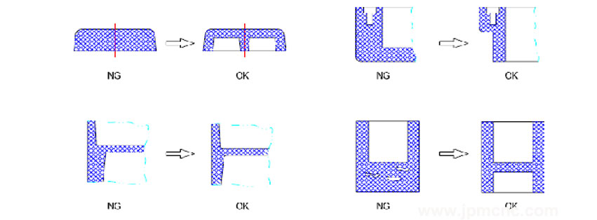
Plastic parts wall thickness design for plastic injection molded parts , Jingxin has15+ years experience in Plastic injection molding
General Thermoplastic molded parts wall thickness
| Minimum thickness and general thickness for each type thermoplastic (unit:mm) | ||||
| Thermoplastic | Minimum thickness | Small parts thickness | Middle parts thickness | Large parts thickness |
| PA | 0.45 | 0.76 | 1.50 | 2.40~3.20 |
| PE | 0.60 | 1.25 | 1.60 | 2.40~3.20 |
| PS | 0.75 | 1.25 | 1.60 | 3.20~5.40 |
| PMMA | 0.80 | 1.50 | 2.20 | 4.00~6.50 |
| PP | 0.85 | 1.45 | 1.75 | 2.40~3.20 |
| PC | 0.95 | 1.80 | 2.30 | 3.00~4.50 |
| POM | 0.45 | 1.40 | 1.60 | 2.40~3.20 |
| PSU | 0.95 | 1.80 | 2.30 | 3.00~4.50 |
| ABS | 0.80 | 1.50 | 2.20 | 2.40~3.20 |
| PC+ABS | 0.75 | 1.50 | 2.20 | 2.40~3.20 |
To learn More about General Thermoplastic Characters & Applications please click here Thermoplastic Injection molding
2.Ribs:
Most of the plastic products should be needed ribs in design which can greatly increase their overall strength without increasing the overall shell thickness of the product. Especially for large products, while also preventing Product deformation. The thickness of the ribs is usually 0.5-0.7 times the overall thickness if more than 0.7 times is easy to shrink. When the height of the ribs is high (above 20mmH), the draft angle of ribs should be 0.5-1 degree at least. If the height of ribs is below 15 mm, no need draft angle to the ribs.
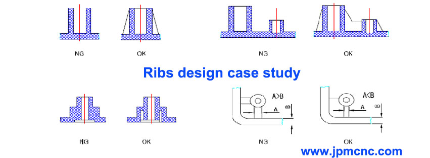
Ribs design for the plastic injection molded parts
3.Draft Angel :
This is an indispensable step in design guidelines for plastic injection molded parts. Plastic products have a draft angle from the ejection direction, but the height is below 4mm(such as a flat) and has special requirements except (but when the sidewall is not a large and no die when the need to do a bit ). The draft angle is usually 1-5 degrees, often take about 2 degrees. Depending on the specific size, height, shape, to be able to successfully mold opening and does not affect the use of the principle of function. Front mold is usually 0.5 degrees greater than the back cavity mold so that the product can remain in the back cavity. Usually, pillow, insert, touch and other places are required to do with the draft angle.
4.Fillet (R corner):
In order to reduce the stress concentration, conducive to the flow of plastic and easy stripping, The edge of Injection molded Plastic parts are required to design in round R0.3-0.5mm except for the special requirements for special function
5.Holes on molded parts:
From the point of view of the mold processing, the hole is best made of simple shape of the circular hole, as far as possible not to make complex shaped holes, hole size should not be too small, hole depth and hole diameter should not be too large since the Long mold easily broken, deformation. The distance between the hole and the edge of the product is preferably greater than 1.5 times the hole diameter. And the distance between two holes is preferably greater than twice the hole diameter so that the product has a good strength.
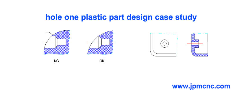
Design guideline for the holes on plastic molded part
6.Boss:
The boss is usually used for the two plastic products in the form of shaft-hole fit or self-tapping screws. When the BOSS is not very high so need design any draft angle for the boss. The BOSS is very high, usually on the outside of the crossbar (ribs), the cross ribs usually do 1-2 degrees draft angle and as same as the BOSS. When the BOSS used for self-tapping screw assembly, the hole diameter of the smaller 0.2-0.4mm than the tapping screw so that the screw can be locked. For example, if tapping screw M3.0, BOSS’s inside hole diameter is usually Ф2.60-2.80mm.
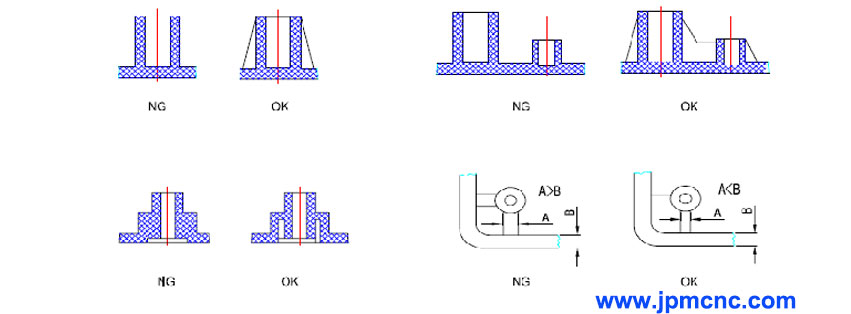
Plastic-boss-design guideline
7.Inserts molding:
When an existing metal or plastic piece is placed in the mold again, the already existing part is called an insert. However the plastic product design has insert parts, it is necessary to consider the insert in the mold must be able to completely, accurate and reliable positioning. This time consider the insert must be connected with the forming part of the solid, when the thickness of the wall around the insert parts is too thin then the inserts is not fixed tightly. But also consider not leak plastic around the inserts.
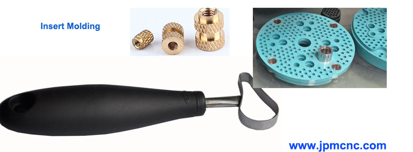
Insert-molding
8.The surface of molded parts:
The molded plastic part surface can be smooth (mold surface polished ). The pattern of fire (the surface of mold cavity made by EDM copper electrical discharge processing), a variety of patterns of the eclipse surface (Texture surface) and carved surface. When the texture or other patterns on the surface is too deep then we should increase the draft angle on mold design.
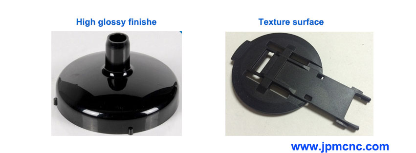
plastic-injection-molded-parts-surface-finish
9.Text:
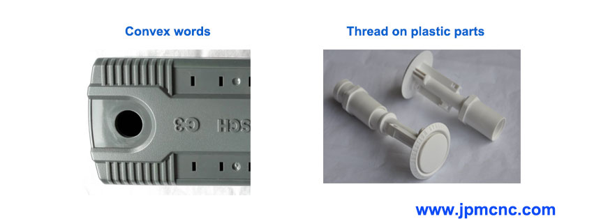
Some time we need put some text inside or outside of the surface Plastic parts the text can be convex words can also be concave words. It is easy to do convex characters in the mold cavity, it is hard to do convex words on mold cavity.
10.Thread:
The thread on Plastic parts is usually not very high precision, the mold needs to do a special thread device for eject. If not high requirement to the thread, the mold can be designed with the structure can be forced to stripping.
convex-words-and-thread-design-guideline-on-plastic-molded-parts-
11.Support surface:
Plastic products usually do not have to do the whole surface of the support surface, but to do a single boss, ribs to do support. Because the plastic product is difficult to achieve the whole of the larger plane since it is easy to deformation warping.
12.The assembly of plastic parts:
12.1. Ultrasonic line assembly method, it is easy to do on the mold with a design, but the assembly process to be made by the specialized ultrasonic machines. Then the cost increases and also cannot be re-assembly or reopen it. Ultrasonic line cross-section is usually made of 0.30 wide and 0.3 high with the shape of triangular, in the length of the direction of 5-10MM with an interrupted 2MM;
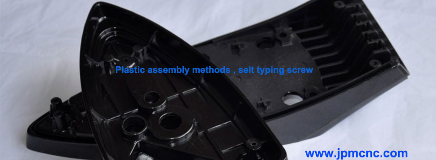
12.2. Self-tapping screw assembly method, it is easy to archive on mold, but the labor cost for assembly is high than Ultrasonic. the finished product can be re-open and re-assembly again.
12.3. Hook – buckle assembly method, which is characterized by more complex mold processing, but easy assembly, and can be repeatedly removed, used many times. There are many forms of hooks, to avoid the hook at the local plastic bit too thick. But also consider the hook at the mold to do mold convenient. The Hook to do with the appropriate fit, easy assembly, and disassembly, the mating surface for the fit, the other side of the appropriate gap.
assembly-design-for-plastic-injection-molded-products
13.Assembly outlook line:
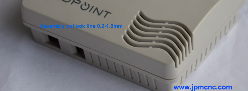
There is an Assembly outlook line between two assembled plastic products, normally the width of the Assembly outlook line often take 0.2-1.0mm. Sometimes it depends on the overall size of the product.
Assembly-outlook-line
14.Plastic parts surface treatment methods:
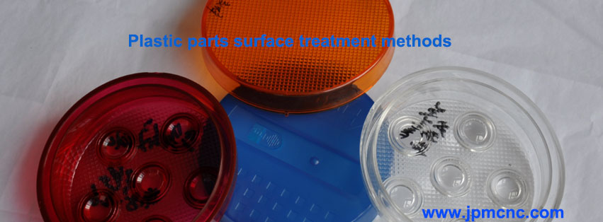
Painting, silk screen printing, heat press, vacuum electroplating, carving, Texture, polishing, dyed color and so on.
Plastic-parts-surface-treatment-methods. More available please visit Finish surface treatment
For more design guidelines for plastic injection molded parts, please visit our website www.jpmcnc.com or contact us at email enquiry@jpmcnc.com, if you have a project please send us for an instant quote.
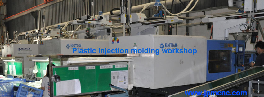
plastic-injection-molding-workshop

